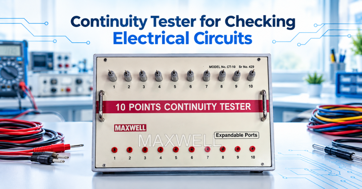
Here’s a basic question that matters more than people realize: before any wire or cable gets trusted to carry current, is the path actually complete? That’s the whole point of a continuity tester. No guessing, no opening things up to look — just a quick check that tells you yes or no.
It’s about as basic as electrical instruments get. And yet it never really goes out of use — someone’s chasing a fault at home, checking wiring on a shop floor, or running through a batch of multi-core cables in a lab. Let’s break down what it does, how it works, and where it sits next to the other tools in an electrician’s or technician’s kit.
It is also mandatory to have it in Testing labs which comply with this standard RCF/EL/0015 REV-D (2020) of Indian Railways as per the document shared by Rail Coach Factory.
What Is a Continuity Tester?
Put simply, a continuity tester checks for a complete, unbroken path between two points in a circuit. It tells you whether current can travel from one end of a conductor all the way to the other, or whether it hits a dead end somewhere along the line.
One thing to keep in mind — the circuit has to be de-energized first, always. This isn’t about checking current flow during normal use. It’s about confirming the physical path itself is intact.
How It Works, Step by Step
The mechanics behind it are honestly pretty simple. Inside there’s usually a small battery, wired in series with an indicator and two test leads.
Touch those leads to two points on a dead circuit, and you get one of two outcomes:
Path’s complete? The circuit closes, current runs from the battery through the indicator, and you get a signal — a light turning on, or that familiar buzz.
Path’s broken somewhere? Nothing flows. The indicator stays dark, and now you know there’s an open circuit to track down.
Funny enough, this is where “buzzing out a circuit” comes from — old-school technicians literally listening for that buzz to figure out which wire goes where.
When One Circuit Isn’t Enough — Multi-Point Testing
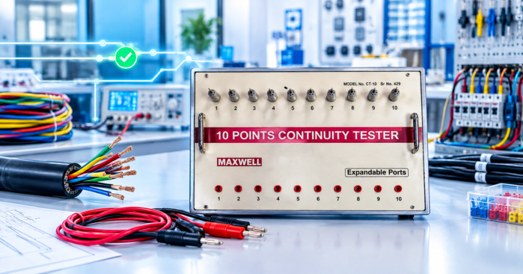
Sometimes you’re not dealing with just one wire. Think multi-core cables, wiring harnesses — several conductors that all need checking. That’s where a multi-point tester comes in handy instead of the basic two-lead kind. A 10-point tester, for example, lets you run through several conductors in one go rather than testing each one separately. In cable manufacturing especially, this saves a ton of time — nobody wants to check every single core in a multi-conductor cable one at a time.
Why This Even Matters
Here’s the thing about broken conductors — they don’t always show themselves. A cable can look totally fine from the outside while there’s a break hiding inside that you’d never catch without actually testing it.
A few things continuity testing catches early:
- Confirming a wire actually connects correctly from one end to the other
- Spotting internal breaks in cables or cords before they cause a bigger problem
- Checking that fuses, switches, and connectors are doing their job (a healthy fuse, for instance, should show continuity)
- Verifying grounding — making sure an exposed conductor or metal chassis is properly earthed
- Figuring out unfamiliar wiring by tracing which points connect to which
Where People Actually Use These
- Troubleshooting — chasing down faults in home or industrial wiring
- Cable manufacturing — catching breaks in multi-core cables before they ship out
- Installation work — confirming wiring runs correctly end to end, especially in a bundle of similar-looking wires
- Quick component checks — fuses, switches, small parts
- Circuit board repair — tracing connections when reverse-engineering or fixing something
Continuity Tester or Just Use a Multimeter?
Fair question, since they get mixed up a lot.
Most multimeters come with a continuity setting built in, usually tied to the ohmmeter function, and they’ll beep when they detect continuity. That’s genuinely handy — one device, multiple jobs.
A dedicated continuity tester is simpler though, and usually cheaper. If you’re doing the same check over and over — say, in a production or QC line — a dedicated tester tends to be quicker than switching a multimeter between modes each time.
Continuity ≠ Resistance
Worth clearing up, because these two get conflated.
A continuity tester just gives pass or fail. Complete path, or not. It won’t tell you what the actual resistance value is.
If the exact number matters — like confirming a cable meets a specific resistance spec — that’s a different instrument’s job. A resistance meter or micro-ohm meter measures the real value, often using something like the 4-terminal Kelvin method for accuracy.
In a lot of setups, honestly, both get used together. Continuity tester for the quick checks across multiple points, resistance meter when the actual numbers need to be right for QC or compliance.
Picking One — What Actually Matters
How many points you’re testing. A single wire? Basic two-lead tester works fine. Multiple conductors at once? Go multi-point — a 10-point model saves real time.
Light or buzzer? Some testers do one, some do both. Honestly, a buzzer is often more practical since you’re not stuck watching the device the whole time.
Build quality. If it’s going into the field or getting used daily, it needs to hold up — decent handle, leads that won’t fray after a few weeks.
What you’re actually doing with it. Quick occasional checks? Routine QC on a cable line? The answer changes what kind of tester actually makes sense.
What Maxwell Offers
Maxwellindia makes a Continuity Tester – 10 Point, built for checking multiple conductors at once in cable and wire testing. It’s the kind of tool that fits naturally alongside something like a digital micro-ohm meter — quick continuity checks on one side, precise resistance numbers when needed on the other.
Wrapping Up
A continuity tester does one thing, and does it well — tells you whether a path is complete, fast, no fuss. Whether that’s tracing a fault at home, checking a fuse, or running through a batch of cables, it earns its place in almost any electrical toolkit. And when pass/fail isn’t enough — when you actually need the resistance number — that’s when a dedicated resistance meter steps in to finish the job properly.
Frequently Asked Questions
1. What does a continuity tester actually check?
Whether there’s a complete, unbroken path between two points in a de-energized circuit — shown with a light or a buzzer.
2. Can it measure resistance too?
No. A basic continuity tester just gives pass/fail. For an actual resistance value, you’d need a dedicated resistance meter or micro-ohm meter.
3. What’s the point of a multi-point tester?
It lets you check several conductors — like the cores in a multi-core cable — at once, instead of one at a time.
4. Isn’t this basically the same as a multimeter?
Close, but not quite. Multimeters often have a continuity function built in, but a dedicated tester is simpler and built for just this one job.
5. Why does the circuit need to be de-energized first?
Because continuity testing relies on the tester’s own power source. Testing a live circuit can fry the tester and put whoever’s holding it at risk.