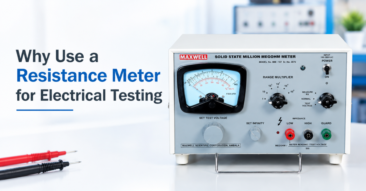
Resistance is one of those electrical properties that sounds simple but tells you an enormous amount about a component’s health. A conductor with unexpectedly high resistance is a conductor that’s about to cause problems — whether that’s excess heat, voltage drop, or outright failure. This is exactly why a resistance meter remains one of the most fundamental instruments in any electrical testing setup.
If you’re wondering why resistance measurement deserves dedicated instrumentation rather than a quick multimeter check, this guide walks through the reasoning, the working principle, and where resistance meters genuinely earn their place in a testing process.
What Is a Resistance Meter?
A resistance meter is an instrument designed to measure the electrical resistance of a conductor, component, or material, typically expressed in ohms, milliohms, or micro-ohms depending on the range involved. It works by applying a known current and measuring the resulting voltage drop, then calculating resistance using Ohm’s Law.
While the term can cover a wide range of instruments — from a basic ohmmeter function on a multimeter to a dedicated micro-ohm meter — the more precise and industrially relevant resistance meters are built specifically to measure very low resistance values accurately, something general-purpose meters simply aren’t designed to do well.
Why Resistance Testing Matters in the First Place
Every electrical connection, conductor, and winding has an expected resistance range. When that resistance drifts outside expected limits, it’s usually a sign of an underlying problem.
- Poor connections — a loose or corroded joint shows up as elevated resistance long before it causes a visible fault
- Conductor defects — manufacturing flaws, incorrect material, or inconsistent cross-section all affect resistance
- Winding faults — shorted or damaged turns in a transformer or motor winding alter the expected resistance value
- Contact wear — switchgear and circuit breaker contacts degrade over time, and rising resistance is often the earliest indicator
In each of these cases, resistance measurement catches the problem well before it turns into equipment failure or a safety incident.
How Does a Resistance Meter Work?
Applying a Known Test Current
The instrument passes a controlled, known current through the sample being tested. The current level is chosen based on the expected resistance range — higher currents are typically used for lower resistance ranges to generate a measurable voltage drop. But it should be optimal otherwise very high currents can increase the temperature of the sample and thus the resistance. While very low current can lead to unstable readings in the resistance meter.
Measuring the Voltage Drop
As current flows through the resistance being tested, it produces a voltage drop across it. The instrument measures this voltage precisely.
Calculating Resistance via Ohm’s Law
Using the relationship R = V/I, the instrument calculates the resistance value from the measured voltage and the known applied current, then displays the result digitally.
The 4-Terminal Kelvin Method for Low Resistance
For low-resistance testing specifically, resistance meters use a 4-terminal Kelvin arrangement — two terminals to apply current, and two separate terminals to sense voltage. This separates the current path from the voltage-sensing path, so lead resistance and contact resistance at the probe tips don’t get included in the measurement. This is the difference between a resistance meter giving you a genuinely accurate reading and a standard 2-wire multimeter giving you a number that’s mostly noise at low resistance ranges.
Temperature Compensation
Since resistance changes with temperature, many resistance meters include an inbuilt temperature sensor that automatically calculates the equivalent resistance at a standard reference temperature, typically 20°C. This allows readings taken at different times or conditions to be compared meaningfully.
Why Use a Dedicated Resistance Meter Instead of a Multimeter?
This is worth addressing directly, since it’s the question most people are actually trying to answer.
A standard multimeter is genuinely useful for general troubleshooting, but it falls short in a few specific ways when it comes to serious resistance testing:
Accuracy at low resistance — multimeters use a 2-wire method, which includes lead and contact resistance directly in the reading. At resistances under a few ohms, this error can be larger than the value you’re trying to measure.
Limited resolution — general-purpose meters often can’t resolve differences at the micro-ohm or milliohm level, which matters a great deal in cable, busbar, and winding testing.
No temperature compensation — without this, comparing readings across different testing sessions or ambient conditions becomes unreliable.
Insufficient test current — dedicated resistance meters apply higher, more stable test currents suited to producing a clean, measurable signal even at very low resistance.
For quick continuity checks, a multimeter is perfectly fine. For anything involving quality control, compliance testing, or diagnosing subtle faults, a dedicated resistance meter is the more reliable tool.
Common Applications of a Resistance Meter
Resistance measurement shows up across a wide range of electrical testing scenarios:
- Cable and conductor testing — verifying that conductor resistance meets specification during manufacturing
- Transformer and motor winding testing — checking coil resistance to detect shorted turns or winding faults
- Switchgear and circuit breaker contact testing — measuring contact resistance to identify wear before it causes overheating
- Busbar and joint testing — confirming low-resistance connections in power distribution systems
- General electrical maintenance — troubleshooting unexplained voltage drops or heating in a circuit
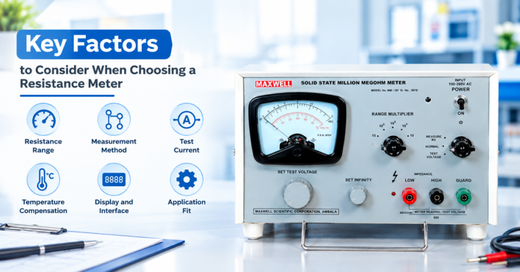
Key Factors to Consider When Choosing a Resistance Meter
1. Resistance Range
Make sure the instrument comfortably covers the range you actually test — from the lowest micro-ohm readings you expect up through higher ranges, without needing a separate instrument for each.
2. Measurement Method
For any serious low-resistance work, confirm the meter uses a genuine 4-terminal Kelvin configuration rather than a basic 2-wire setup.
3. Test Current
Check the test current available at your typical resistance range — a higher current generally improves reading stability at very low resistances.
4. Temperature Compensation
An inbuilt sensor with automatic compensation to a standard reference temperature removes a significant source of manual error, especially in cable and conductor testing.
5. Display and Interface
A clear digital display makes routine, repetitive testing faster and reduces the chance of misreading values during high-volume quality checks.
6. Application Fit
Consider what you’ll primarily be testing — cables, windings, contacts, or busbars — since terminal design and fixture requirements can vary based on the sample type.
Resistance Meter vs. Other Related Instruments
It helps to place the resistance meter in context alongside a few related instruments.
A resistance meter or micro-ohm meter measures the actual resistance value of a conductor or component in ohms.
A conductivity meter takes that resistance measurement further, combining it with sample dimensions to calculate how conductive the material itself is relative to a reference standard.
An insulation resistance tester, such as a million megohm meter, measures resistance in the opposite context — checking that current does not leak through insulation, rather than confirming it flows correctly through a conductor.
Used together, these instruments give a complete view of an electrical system: confirming that current flows properly where it should, that the material itself meets conductivity expectations, and that it stays contained where it shouldn’t escape.
Resistance Meters at Maxwell
Maxwellindia manufactures digital micro-ohm meters, including the DM-121, designed for accurate low-resistance measurement using the 4-terminal Kelvin method, with an inbuilt temperature sensor for automatic compensation to a standard 20°C reference. These instruments are built for cable, conductor, transformer, and general electrical component testing, where standard multimeters simply don’t offer the precision needed for reliable quality control.
Conclusion
A dedicated resistance meter earns its place in electrical testing precisely where general-purpose meters fall short — at low resistance values, where lead resistance, contact resistance, and temperature variation can otherwise make readings meaningless. Whether you’re testing cable conductors, transformer windings, or switchgear contacts, using a proper resistance meter with a 4-terminal Kelvin method and temperature compensation gives you readings you can actually trust, and that’s ultimately what good electrical testing comes down to.
Frequently Asked Questions
1. Why can’t I just use a multimeter to measure low resistance?
A multimeter uses a 2-wire method, which includes lead and contact resistance in the reading. At low resistance values, this error can be larger than the actual resistance being measured, making a dedicated resistance meter necessary for accuracy.
2. What is the 4-terminal Kelvin method used in resistance meters?
It’s a measurement technique using separate terminals for applying current and sensing voltage, which eliminates the effect of lead and contact resistance on the reading — essential for accurate low-resistance measurement.
3. Why does temperature affect resistance readings?
Conductor resistance naturally changes with temperature, which is why resistance meters with automatic temperature compensation calculate an equivalent value at a standard reference temperature, allowing consistent comparisons.
4. What is a resistance meter commonly used for?
It’s widely used for testing cable and conductor resistance, transformer and motor winding checks, switchgear and circuit breaker contact resistance, and general electrical maintenance and troubleshooting.
5. How is a resistance meter different from a conductivity meter?
A resistance meter measures the resistance of a specific sample in ohms. A conductivity meter uses that resistance along with the sample’s dimensions to calculate how conductive the material itself is compared to a reference standard.