Drawing Dies Measurement: Methods, Instruments, and Importance in Wire & Tube Manufacturing
Introduction
Drawing dies are one of the most critical tooling components in metal forming industries. Whether it is wire manufacturing, tube drawing, rod drawing, or profile drawing, the final quality of the product depends heavily on the accuracy, condition, and consistency of the drawing die. Even a few microns of deviation in die dimensions can lead to serious quality issues such as incorrect diameter, surface defects, excessive wear, or frequent wire breakage.
Because of this, drawing dies measurement is not just a quality control activity—it is a fundamental process that directly affects productivity, material cost, tool life, and compliance with national and international standards.
This blog explains:
- What drawing dies are
- Why precise measurement is essential
- Key parameters that must be measured
- Measurement methods and instruments
- Applications in wire, tube, and related manufacturing industries
What Are Drawing Dies?
Drawing dies are precision tools used to reduce the cross-sectional area of metal by pulling it through a specially shaped opening. The die forces the material to deform plastically while maintaining dimensional accuracy and surface quality.
Common Types of Drawing Dies
- Wire drawing dies – For electrical wires, conductors, cables
- Tube drawing dies – For seamless and welded tubes
- Rod drawing dies – For bars and solid sections
- Profile drawing dies – For special cross-sectional shapes
Die Materials
- Tungsten Carbide (TC)
- Polycrystalline Diamond (PCD)
- Natural Diamond
- Tool Steel (for low-duty applications)
Each material has different wear characteristics, making regular measurement essential.
Why Is Drawing Dies Measurement Important?
1. Dimensional Accuracy of Final Product
The die opening directly defines the final diameter or profile of the wire or tube. Incorrect die size leads to:
- Over-sized or under-sized products
- Rejection during inspection
- Customer complaints
2. Tool Life and Cost Control
Improper die geometry causes:
- Uneven wear
- Cracks or chipping
- Frequent die replacement
Accurate measurement helps detect wear early and allows repolishing or reconditioning, saving cost.
3. Process Stability
Incorrect die angles or bearing lengths increase:
- Drawing force
- Heat generation
- Wire breakage
Precise die measurement ensures smooth drawing and stable production.
4. Compliance with Standards
Many industries follow IS, ASTM, DIN, ISO, or IEC standards for wire and tube dimensions. Die measurement ensures compliance.
Key Parameters in Drawing Dies Measurement


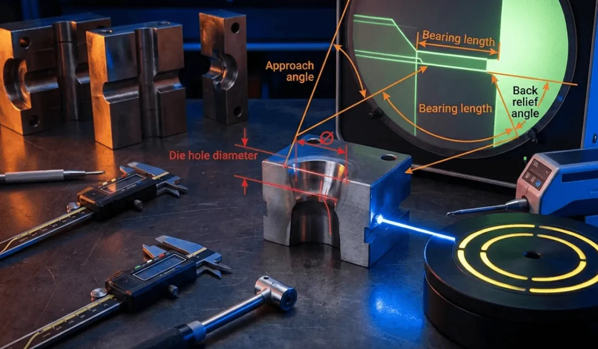
1. Die Hole Diameter
The most critical parameter.
- Measured at the bearing zone
- Typically controlled in microns
- Directly affects final wire or tube size
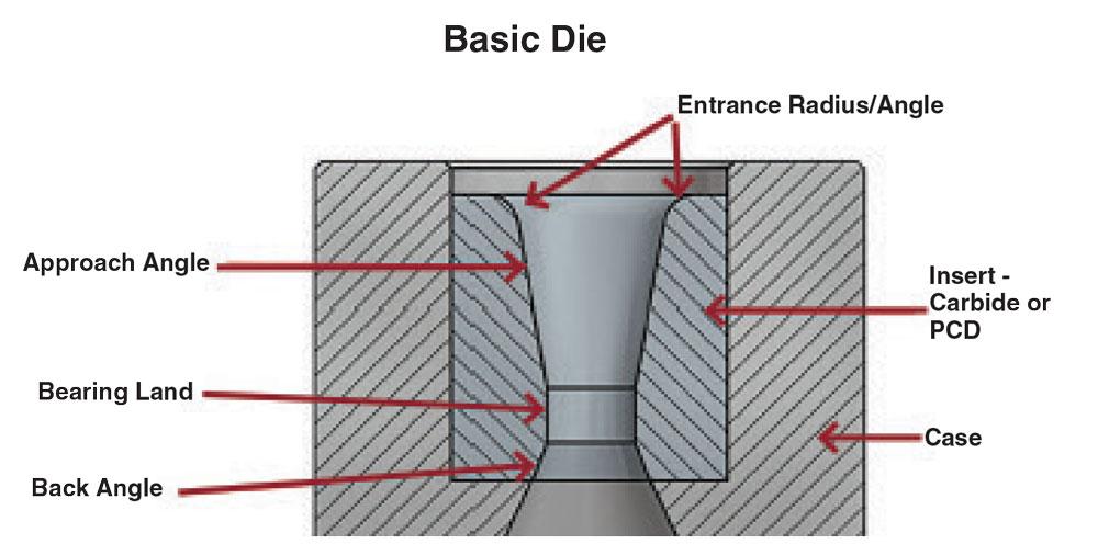
2. Die Angle (Approach Angle)
- Controls metal flow and deformation
- Too small → excessive friction
- Too large → poor surface finish
Common approach angles:
- Wire drawing: 8° to 16°
- Tube drawing: varies based on material and reduction
3. Bearing Length
- Maintains dimensional stability
- Excessive bearing increases friction
- Insufficient bearing causes size fluctuation
4. Back Relief Angle
- Helps reduce friction after drawing
- Prevents die damage during wire exit
5. Surface Finish
- Scratches or pits cause wire marks
- Measured in Ra or visually inspected under magnification
6. Roundness and Concentricity
- Important for electrical and precision applications
- Poor roundness leads to uneven current distribution or mechanical imbalance
Drawing Dies Measurement Instruments

1. Optical Profile Projector
Profile projectors are widely used for:
- Measuring die angles
- Checking hole geometry
- Inspecting bearing length
- Comparing actual die profile with master templates
Advantages
- Non-contact measurement
- High magnification
- Ideal for small dies
Limitations
- Operator-dependent
- Limited depth measurement
2. Toolmaker’s Microscope
Used for:
- Precision diameter measurement
- Angle measurement
- Surface defect inspection
Toolmaker microscopes offer higher accuracy than profile projectors and are suitable for quality labs and die manufacturers.
3. Bore Gauges and Pin Gauges
- Pin gauges: Quick go/no-go inspection
- Bore gauges: For internal diameter measurement
Best for
- Shop-floor checks
- Production monitoring
Limitations
- Limited accuracy for very small diameters
- No profile information
4. Air Gauges (Pneumatic Measurement)
Air gauges are extremely popular in wire drawing die inspection.
Why air gauges?
- High repeatability
- Sub-micron resolution
- Fast measurement
They are ideal for:
- Bearing diameter measurement
- Wear monitoring
5. Vision Measuring Systems (VMS)
Vision systems combine optics and software to measure:
- Die diameter
- Angles
- Roundness
- Profile deviations
Advantages
- Automated measurement
- Digital data storage
- Reduced human error
6. Coordinate Measuring Machines (CMM)
Used mainly for:
- Complex die profiles
- High-precision R&D applications
Limitations
- Expensive
- Less suitable for very small die holes unless specialized probes are used
Drawing Dies Measurement in Wire Manufacturing
In wire manufacturing, dies determine:
- Electrical resistance
- Mechanical strength
- Surface quality
- Current carrying capacity (ampacity)
Typical Wire Applications
- Copper conductors
- Aluminium wires
- Steel wires
- Alloy wires
Measurement Focus Areas
- Final diameter tolerance
- Roundness
- Surface finish
- Die wear progression
Regular die measurement ensures:
- Consistent wire resistance
- Better annealing results
- Lower scrap generation
Drawing Dies Measurement in Tube Manufacturing

Tube drawing is more complex because it involves:
- Outer diameter control (die)
- Inner diameter control (mandrel or plug)
Key Measurement Parameters
- Die entry angle
- Bearing diameter
- Die alignment
- Surface condition
Why Measurement Is Critical
- Ovality control
- Wall thickness uniformity
- Leak prevention
- Pressure resistance compliance
Tube manufacturers rely heavily on optical and pneumatic measurement systems to maintain consistency.
Common Problems Due to Poor Die Measurement
- Frequent wire breaks
- Excessive lubricant consumption
- High power consumption
- Poor surface finish
- Dimensional rejection
- Reduced die life
All of these issues trace back to inaccurate or infrequent die measurement.
Frequency of Drawing Dies Measurement
| Stage | Measurement Frequency |
|---|---|
| New die inspection | 100% inspection |
| During production | Periodic (shift-wise or batch-wise) |
| After re-polishing | Mandatory |
| Before reuse | Mandatory |
A structured inspection schedule significantly improves process reliability.
Calibration and Traceability
Measurement instruments used for die inspection must be:
- Calibrated regularly
- Traceable to national/international standards
- Maintained under controlled conditions
This is especially important for:
- Export-oriented manufacturers
- ISO 9001 / IATF 16949 certified facilities
- Electrical and aerospace applications
Automation and Digitalization in Die Measurement
Modern manufacturing is moving towards:
- Digital measurement records
- SPC (Statistical Process Control)
- Automated inspection systems
Benefits include:
- Trend analysis of die wear
- Predictive maintenance
- Reduced downtime
- Improved audit readiness
Conclusion
Drawing dies measurement is a critical quality control activity that directly impacts wire and tube manufacturing efficiency, product quality, and operational cost. From simple pin gauges to advanced vision systems and air gauges, the right measurement approach depends on:
- Die size
- Accuracy requirement
- Production volume
- Industry standards
For manufacturers aiming at high consistency, low rejection, and long die life, investing in accurate and repeatable drawing die measurement systems is not optional—it is essential.
By implementing proper inspection methods, maintaining calibrated instruments, and monitoring die wear proactively, industries can achieve stable production, superior product quality, and long-term cost savings