Conductor / Cable Resistance: Complete Guide for Engineers, Technicians & QA Teams
In every electrical installation—whether it is low-voltage wiring, instrumentation cabling, HT power distribution, automotive harnessing, or telecom networks—the resistance of a conductor plays a crucial role. Cable resistance directly affects power loss, voltage drop, heating, efficiency, and long-term reliability of the system.
Despite being a basic parameter, many technicians, manufacturers, and installers face difficulty in accurately measuring cable resistance. Factors like cable length, temperature, test setup, instrument precision, contact resistance, and material purity often lead to wrong readings.
This detailed guide covers everything you need to know about conductor resistance, including fundamentals, calculation methods, industry standards, measurement techniques, common issues, and troubleshooting with practical tips.
1. What Is Conductor / Cable Resistance?
Conductor resistance refers to the opposition a cable offers to the flow of electrical current. It depends mainly on the material, length, cross-sectional area, and temperature of the conductor.

The formula is: R = ρ * L / A
Where:
- R = Resistance (Ω)
- ρ = Resistivity of material
- L = Length of conductor
- A = Cross-sectional area
Typical resistivity values:
- Copper: 0.017241 Ω·mm²/m
- Aluminium: 0.028264 Ω·mm²/m

Good quality copper cables exhibit very low resistance, which makes them preferred for power transmission and distribution.
2. Why Cable Resistance Matters
Cable resistance affects almost every performance parameter of an electrical system.
2.1 Voltage Drop
Higher resistance results in:
- Higher drop across long cables
- Reduced voltage at load
- Issues with motors, heaters, instrumentation
2.2 Power Loss
Power loss due to resistance:
P=I²R
A small increase in R can cause high heat generation.
2.3 Heating & Insulation Stress
Excessive resistance increases conductor temperature, leading to:
- Faster insulation ageing
- Reduced life of cable
- Fire hazards
2.4 Efficiency
Lower resistance = better energy efficiency
2.5 Quality Control
Manufacturers must ensure conductor resistance is within IS/IEC limits.
3. Standards for Conductor Resistance
Several national and international standards specify maximum allowable conductor resistance:
Indian Standards (IS)
- IS 694 – PVC insulated cables
- IS 1554 – XLPE and PVC power cables
- IS 8130 – Conductor requirements
- IS 14255 – Measuring methods of low resistance
IEC Standards
ASTM Standards
These standards ensure proper measurement methods and quality compliance.
4. Accepted Tolerances
Typically:
- For copper stranded conductors: +5% tolerance from nominal
- For aluminium conductors: +7%
- Temperature correction required to 20°C standard
IS 8130 defines maximum DC resistance for various conductor sizes.
5. Why Many People Face Issues Measuring Cable Resistance
This is one of the biggest challenges in cable QC. Users often complain:
“Resistance value is high; cable seems faulty.”
“Two technicians get two different readings.”
“Reading keeps fluctuating.”
“Thick cables show weird readings.”
The truth: Most of these issues are due to improper measuring practices—not defective cables.
Here are the 12 most common reasons:

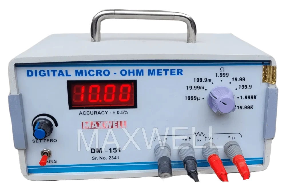
5.1 Using a Multimeter Instead of a Proper Micro-Ohm Meter
A multimeter is not suitable for low-ohm measurement (<1 Ω).
Reasons:
- Low test current
- Poor resolution
- Not 4-wire Kelvin method
- Huge contact resistance errors
Solution: Use a 4-Wire Micro Ohm Meter.
5.2 Not Using 4-Wire Kelvin Method
2-wire adds lead resistance into the measurement.
For cables, this error becomes huge.
5.3 Poor Contact Between Clips and Conductor
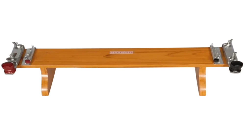
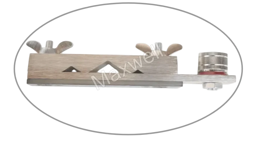
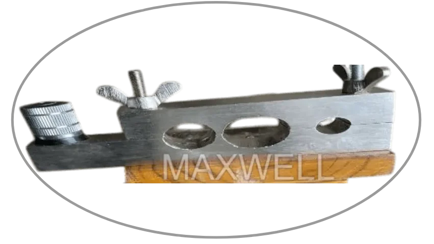
If crocodile clips touch PVC instead of copper or are loosely fitted, readings shoot up. It is preferred to use 1 meter wooden attachment with provision to use banana plugs for establishing contacts.
5.4 Oxidized or Dirty Conductor Surface
Oxidation increases interface resistance.
Solution: Clean the conductor, scrape lightly by using a sandpaper. Making sure that the diameter of the conductor won’t reduces.
5.5 Stranded Conductor Compression
If current and sense probes touch only top strands, resistance increases.
Solution: Use proper clamping system with different fixture setup for flat, vector shaped or circular conductors.
5.6 Optimal Test Current
Lower test current gives unstable or inconsistent reading. While higher current increases temperature of the cable leading to change in resistance value.
Check IS standards for checking the optimal test current value or contact instrument manufacturer for details. Generally micro ohm meter comes with 2 ampere output current rating for low value ranges.

5.7 Long Cable Length – Poor Handling
Coiled cables may cause:
- Mutual inductance
- Twisting
- Partial shorting between strands
Always test cable fully straightened. This is the reason why some micro-ohm meters don’t show readings when tested on Drum length of cables.
Preferably, one should use clamping system for better gripping or long(undefined) length of the cable.
5.8 Temperature Variation
Resistance varies 0.4% per degree Celsius for copper.
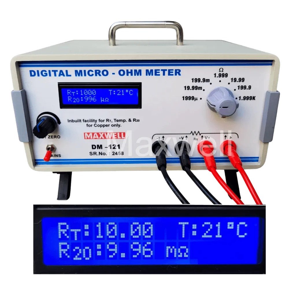
Always apply temperature correction to 20°C by referring table as per IS 8130. Or buy micro-ohm meter with built in temperature compensation feature which directly shows Resistance at 20°C. For ex. DM-121 from Maxwell
5.9 Incorrect Length Measurement
Resistance is proportional to length. Even 1 meter error can cause mismatch. Use standard wooden attachment with scale inbuilt.
5.10 Material Mismatch
Copper vs Aluminium reading confusion is very common.
5.11 Wrong Cross-sectional Area Knowledge
Manufacturers sometimes supply:
- Nominal area not equal to actual
- Higher strand diameter tolerance
This changes resistance.
5.12 Instrument Not Calibrated
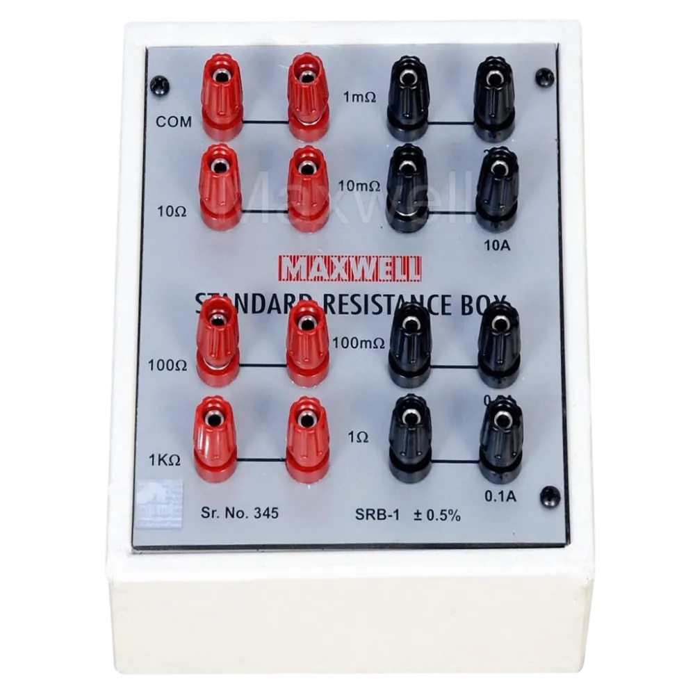
Always ensure the micro-ohm meter / Kelvin Double Bridge is recent calibrated.
Standard Resistance Box can be used for calibration of these instruments
6. How to Measure Conductor Resistance Correctly
Here is the correct, industry-standard way.
6.1 Instruments Required
- Kelvin 4-Terminal Micro Ohm Meter (0.1 µΩ resolution)
- Test current: 0.1A to 10A depending on cable size
- Kelvin clips or probes
- Measuring tape
- Temperature meter
- Straight measurement bench or flat surface
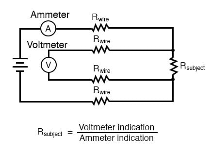
6.2 4-Wire Measurement Setup
Why 4-Wire Method?
It eliminates lead and contact resistance by separating current and sense paths.
Connection Steps
- Identify one end of cable as Point A, other as Point B.
- Connect current leads (C1, C2) to both ends.
- Connect sense leads (P1, P2) between them exactly at the conductor exposure points. The resistance calculated will be the resistance between these 2 points.
- Apply test current.
- Wait for stabilized reading.
- Record resistance.
7. Temperature Correction to 20°C as per IS 8130
Cable resistance must be reported at 20°C for both Copper and Aluminium
R20 = RT / [1+α(T−20)]
R20 = Resistance at 20°C as per required by reports generated according to IS 8130
RT = Resistance at temperature (T) (in °C)
α = 0.004 (as per IS 8130 Page 15)
T = Conductor Temperature in °C
Example:
Measured resistance at 30°C = 0.50 Ω
R20 = 0.50 / [1+0.004(30−20)]
≈ 0.480Ω
Instead of manually calculating the R20 every time. One can use micro-ohm meter with automatic temperature compensation facility. For example – Maxwell DM-121
8. How to Calculate Conductor Resistance (Theoretical)
For copper:
R = 0.017241 * L / A
Example:
A 100m long 6 mm² copper cable:
R = 0.017241×100/6 = 0.287 Ω
Compare this with measured value after temperature correction.
9. Typical Resistance Values for Common Cable Sizes (Copper, 20°C)
| Conductor Size (mm²) | Resistance (Ω/km) |
|---|---|
| 1.5 | 12.10 |
| 2.5 | 7.41 |
| 4 | 4.61 |
| 6 | 3.08 |
| 10 | 1.83 |
| 16 | 1.15 |
| 25 | 0.727 |
| 35 | 0.524 |
| 50 | 0.387 |
| 70 | 0.268 |
| 95 | 0.193 |
| 120 | 0.153 |
| 150 | 0.124 |
| 185 | 0.0991 |
| 240 | 0.0754 |
These are taken from IS 8130 & IEC 60228.
10. Resistance Test Method as per IS 10810-43
Indian standard specifies:
- Test shall be done using DC current.
- 4-terminal Kelvin method mandatory.
- Length must be measured accurately.
- Temperature correction required to 20°C.
- Allowable resistance shall not exceed values of IS 8130.
11. Common Mistakes & Corrective Actions
Mistake 1: Clips put far from the cut point
- Causes extra length → higher resistance
Fix: Place probes exactly at conductor exposure.
Mistake 2: Measuring coiled cable
Induces inductive errors and uneven current flow.
Fix: Straighten cable.
Mistake 3: Using Low-Quality Instruments
Cheap multimeters give completely wrong results.
Fix: Use certified micro-ohm meters equipped with 4-wire measurement method.
Mistake 4: Not accounting for temperature
Resistance at 35°C looks higher than standard references at 20°C.
Fix: Always temperature-correct as per IS 8130.
Mistake 5: Aluminium cable tested as copper
Aluminium has ~60% higher resistance.
Mistake 6: Loose strands or uncompressed conductor
Contact area changes → inconsistent readings.
12. Why Conductor Resistance Increases Over Time
Some users see resistance rising in cables that have been in service for years.
Reasons:
- Oxidation
- High temperature cycles
- Loosened connections
- Strand breakage
- Moisture ingress
For old installations, periodic testing is recommended.
13. Cable Resistance in Power Distribution
A major design parameter for:
- Transformers to DB voltage drop
- Motor starting
- UPS wiring
- Solar plant DC wiring
- EV charging cables
- Industrial machines
Voltage drop calculations depend primarily on cable resistance.
14. Cable Resistance in Data & Telecom
For telephone, LAN, instrumentation, and control cables:
- High resistance causes signal loss
- Affects impedance
- Affects attenuation (dB/km)
Cat5e/Cat6 cables have specific DC resistance requirements.
15. How Manufacturers Ensure Low Resistance
Cable manufacturers follow strict processes:
15.1 Using high purity 99.97% ETP copper
Better conductivity.
15.2 Proper annealing
Ensures uniformity and ductility.
15.3 Accurate stranding
Reduces gaps, improves cross-section consistency.
15.4 Tinned copper coating
Reduces surface oxidation.
15.5 Online monitoring
Laser diameter measurement and spark testing.
15.6 Final resistance testing
100% testing for Power, House wiring, Multi-core cables.
Maxwell India provides advanced micro-ohm meters, Kelvin testers, and cable testing instruments to meet these standards.
16. How to Reduce Cable Resistance (Practical Tips)
If the measured resistance is too high, check these:
✔ Increase conductor size
A larger cross-section reduces resistance.
✔ Use high-purity copper
Avoid recycled or impure material.
✔ Reduce length
Shorter run = lower resistance.
✔ Crimp properly
Loose lugs increase interface resistance.
✔ Keep conductor clean
Remove oxidation.
✔ Avoid overheating
High temperature permanently increases resistance.
17. Case Studies (Realistic Scenarios)
Case 1: 120 mm² Cable Failing in QC Lab
Issue: Resistance measured higher than standard.
Investigation:
- Cable was tested coiled on drum.
- Temperature was 34°C.
- Length assumed incorrectly.
- Tight clamping of the cable checked again
After corrections, resistance passed.
Case 2: Installer Complained 6mm² Cable Overheating
Cause:
- Actual length was 3× longer than design.
- Resistance increased → voltage drop increased.
Solution:
- Use 10mm² cable for long run.
Case 3: Solar EPC Getting Low Voltage at Inverter
Cause:
- Using aluminium cable but design assumed copper values.
Fix:
- Re-calculate voltage drop using aluminium resistivity.
18. Frequently Asked Questions (FAQ)
Q1. How much resistance should a cable have?
Depends on size, material, and length. Refer IS 8130 values.
Q2. Multimeter shows 0 Ω. Is cable perfect?
No. Multimeter resolution too low.
Or decrease the range of the micro-ohm meter. Check values at milli ohm or micro ohm ranges to be double sure.
Q3. Why do two people get different readings?
Due to poor contact, temperature variation, instrument type, not setting zero prior to resistance testing in micro-ohm meter.
Q4. Why does resistance increase in thicker cables?
It doesn’t. Thicker cables have lower resistance.
If high reading → measurement issue.
Q5. Why is 4-wire method necessary?
Eliminates lead/contact resistance. 4 wire Kelvin method is better than 2 wire method for accurate reading.
19. Conclusion
Cable and conductor resistance is one of the most important parameters for electrical performance, safety, and compliance. But most inaccurate readings happen not because the cable is defective, but due to incorrect measurement techniques.
To ensure accuracy:
- Use proper 4-wire Kelvin method
- Follow IS and IEC standards
- Apply temperature correction
- Use reliable micro-ohm meters
- Ensure good contact and correct length
With the right knowledge and tools, measuring conductor resistance becomes simple, consistent, and error-free.