Schering Bridge: Principle, Working, Applications, Advantages, and Standards
Introduction to Schering Bridge
The Schering Bridge is one of the most important AC bridge circuits used in electrical and electronic measurements. It is primarily designed for the measurement of capacitance and dielectric loss (dissipation factor) of insulating materials. Since its invention, the Schering Bridge has played a critical role in high-voltage engineering, insulation testing, cable testing, transformer diagnostics, and material research laboratories.
In industries where insulation quality determines safety, performance, and compliance, accurate measurement of capacitance, dielectric constant, and loss angle becomes essential. The Schering Bridge provides a precise, stable, and reliable method for such measurements and continues to be referenced in international testing standards.
This article provides a detailed, in-depth explanation of the Schering Bridge, including its principle, circuit configuration, working, mathematical analysis, advantages, limitations, applications, standards, and practical considerations, making it a comprehensive reference for engineers, students, calibration professionals, and testing laboratories.
What is a Schering Bridge?
A Schering Bridge is an AC bridge circuit used to measure:
- Unknown capacitance
- Dielectric loss of insulating materials
- Dissipation factor (tan δ)
- Quality of insulation
Unlike DC bridges such as Wheatstone Bridge (used for resistance measurement), the Schering Bridge operates on alternating current, making it suitable for evaluating capacitive components and insulation behavior under AC conditions.
The bridge is particularly useful for high-voltage insulation testing, where accurate determination of dielectric losses is critical.
Why Schering Bridge is Used
The Schering Bridge is widely used because:
- Capacitance cannot be measured accurately using DC methods
- Insulating materials exhibit losses under AC voltage
- High-voltage equipment requires precise insulation diagnostics
- Dielectric properties vary with frequency and temperature
- Dissipation factor measurement helps detect aging, moisture ingress, and defects
In practical terms, Schering Bridge testing helps answer questions such as:
- Is the insulation healthy?
- Has the dielectric deteriorated?
- Is the cable or transformer safe for operation?
- Does the insulation meet standard requirements?
Principle of Schering Bridge
The Schering Bridge operates on the null balance principle, similar to other bridge circuits.
Fundamental Principle
At balance condition, the ratio of impedances in one pair of opposite arms is equal to the ratio of impedances in the other pair of opposite arms.
Mathematically:
When the bridge is balanced:
- No current flows through the detector
- The bridge output voltage is zero
- Unknown parameters can be calculated using known values
The key difference in Schering Bridge is that capacitive and resistive elements are combined to represent real dielectric behavior.

Construction of Schering Bridge
The Schering Bridge consists of four arms, supplied by an AC voltage source.
Bridge Arms Description
- Arm 1 (Test Arm)
- Contains the unknown capacitor (Cx)
- Includes dielectric loss resistance (Rx) in series
- Represents the insulation under test
- Arm 2 (Standard Capacitor Arm)
- Contains a loss-free standard capacitor (Cs)
- High accuracy and stable over temperature
- Used as reference
- Arm 3 (Resistive Arm)
- Contains a non-inductive resistor (R3)
- Used for balancing the bridge
- Arm 4 (RC Combination Arm)
- Contains a resistor (R4) and capacitor (C4)
- Used for phase and magnitude balancing
Detector and Supply
- AC voltage source (fixed frequency)
- Null detector (vibration galvanometer, headphones, or phase-sensitive detector)
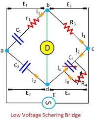
Circuit Diagram Explanation
While the exact diagram may vary, the general Schering Bridge configuration includes:
- Unknown capacitance in one arm
- Known standard capacitor in the opposite arm
- Adjustable resistor and capacitor for balancing
- Detector connected between the bridge junctions
This configuration allows independent balancing of resistive and reactive components, enabling accurate dielectric loss measurement.
Working of Schering Bridge
Step-by-Step Working
- AC supply is applied to the bridge
- Current flows through all four arms
- The detector senses imbalance voltage
- R and C values are adjusted
- Bridge reaches balance (detector shows null)
- Unknown parameters are calculated using balance equations
At balance condition:
- Phase angle between voltage and current is compensated
- Reactive and resistive components are separated
- Dielectric properties are accurately determined
Mathematical Analysis of Schering Bridge
Let:
- Unknown capacitor = Cx
- Dielectric loss resistance = Rx
- Standard capacitor = Cs
- Adjustable resistor = R3
- Adjustable resistor = R4
- Adjustable capacitor = C4
- Angular frequency = ω
At balance condition:
Separating real and imaginary parts gives:
Capacitance Equation
Dielectric Loss Resistance
Dissipation Factor (Tan δ)
One of the most important parameters measured using Schering Bridge is the dissipation factor, also known as tan delta (tan δ).
What is Dissipation Factor?
Dissipation factor represents the energy lost as heat in an insulating material when subjected to an AC electric field.
Importance of Tan δ
- Indicates insulation quality
- Higher tan δ → Poor insulation
- Used for condition monitoring
- Helps detect moisture, contamination, and aging
Advantages of Schering Bridge
The Schering Bridge offers several advantages that make it a preferred method for dielectric measurements.
Key Advantages
- High accuracy in capacitance measurement
- Direct measurement of dielectric loss
- Suitable for high-voltage testing
- Uses stable standard capacitors
- Independent balancing of resistive and reactive components
- Widely accepted in international standards
- Suitable for laboratory and field testing
Limitations of Schering Bridge
Despite its advantages, the Schering Bridge has some limitations.
Limitations
- Requires stable frequency supply
- Manual balancing can be time-consuming
- Sensitive to stray capacitance
- Not suitable for very low capacitance values without shielding
- Requires skilled operation for accurate results
Modern digital instruments often automate these functions, but the fundamental principle remains based on Schering Bridge.
Applications of Schering Bridge
The Schering Bridge finds applications across electrical engineering, material science, power systems, and quality control.
Major Applications
1. Insulation Testing
- Cables
- Transformers
- Bushings
- Switchgear
- Capacitors
2. Dielectric Material Testing
- Plastics
- Rubber
- Paper insulation
- Ceramics
- Oils and resins
3. High-Voltage Engineering
- Power transmission equipment
- Substation components
- Generator insulation
4. Research and Development
- Dielectric characterization
- Material comparison
- Aging studies
5. Educational Institutions
- Engineering laboratories
- Demonstration of AC bridge principles
Schering Bridge in Cable Testing
In cable manufacturing and testing industries, the Schering Bridge is used to:
- Measure cable capacitance per unit length
- Detect insulation defects
- Evaluate dielectric loss
- Ensure compliance with standards
This is particularly important for XLPE, PVC, and EPR insulated cables.
Schering Bridge vs Other AC Bridges
Schering Bridge vs Maxwell Bridge
| Parameter | Schering Bridge | Maxwell Bridge |
|---|---|---|
| Measures | Capacitance & dielectric loss | Inductance |
| Frequency | Fixed AC | AC |
| Application | Insulation testing | Coil measurement |
| Loss Measurement | Yes | Limited |
Schering Bridge vs De Sauty Bridge
| Parameter | Schering Bridge | De Sauty Bridge |
|---|---|---|
| Dielectric loss | Measured | Not measured |
| Accuracy | High | Lower |
| Practical use | Industrial & labs | Educational |
Modern Digital Schering Bridge Instruments
With advancements in electronics, traditional Schering Bridges have evolved into digital capacitance and tan delta testers.
Features of Modern Instruments
- Automatic balancing
- Digital display
- Microprocessor-based calculations
- Data logging
- USB/PC connectivity
- High-voltage testing capability
- Compliance with IEC/IS standards
However, even modern instruments internally operate on Schering Bridge principles.
Standards Related to Schering Bridge Testing
Schering Bridge measurements are referenced in several national and international standards.
International Standards
- IEC 60250 – Dielectric properties measurement
- IEC 60093 – Resistivity of insulating materials
- IEC 60885 – Electrical tests on cables
- IEEE 286 – Power factor and insulation testing
Indian Standards
- IS 13585 – High voltage test techniques
- IS 900 – Electrical insulation testing
- IS 722 – Rubber insulation properties
Compliance with these standards ensures accuracy, reliability, and global acceptance of test results.
Factors Affecting Schering Bridge Measurements
To obtain accurate results, several factors must be controlled:
- Temperature
- Humidity
- Frequency stability
- Stray capacitance
- Shielding and grounding
- Quality of standard capacitor
Proper test setup and calibration are essential.
Calibration of Schering Bridge
Calibration ensures traceability and accuracy.
Calibration Practices
- Use traceable standard capacitors
- Periodic verification
- Environmental control
- Calibration as per ISO/IEC 17025
Calibration laboratories play a critical role in maintaining measurement confidence.
Safety Considerations
When used for high-voltage testing:
- Proper grounding is essential
- Use shielded cables
- Follow HV safety procedures
- Use interlocks and emergency cut-offs
Future of Schering Bridge Measurements
Although modern digital instruments dominate the market, the Schering Bridge principle remains timeless.
Future developments include:
- AI-based insulation diagnostics
- Automated condition monitoring
- Integration with SCADA systems
- Predictive maintenance tools
Frequently Asked Questions (FAQs)
1. What is a Schering Bridge used for?
It is used to measure capacitance and dielectric loss of insulating materials.
2. What does tan delta indicate?
It indicates insulation quality and energy loss.
3. Is Schering Bridge used for DC?
No, it is strictly an AC measurement bridge.
4. Can it measure high voltage insulation?
Yes, it is widely used for high-voltage insulation testing.
5. What type of capacitor is used as standard?
A loss-free, stable standard capacitor.
6. Is Schering Bridge still relevant today?
Yes, modern digital testers are based on the same principle.
7. What industries use Schering Bridge?
Power, cable manufacturing, R&D labs, educational institutes.
8. How accurate is Schering Bridge?
Very high accuracy when properly calibrated.
9. Can dielectric constant be measured?
Yes, indirectly using capacitance values.
10. What frequency is used?
Typically power frequency or specified test frequency.
Conclusion
The Schering Bridge remains a fundamental and indispensable tool in electrical and insulation measurements. Its ability to accurately measure capacitance and dielectric loss makes it essential for quality control, safety assurance, and research applications.
Even with the rise of digital instrumentation, the principles of the Schering Bridge continue to form the backbone of modern tan delta and capacitance testing equipment. For industries focused on reliability, compliance, and performance, understanding and applying Schering Bridge measurements is not just beneficial—it is essential.