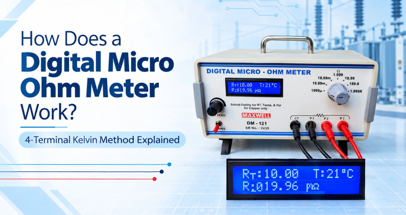
If you’ve ever tried measuring a very small resistance with a regular multimeter, you already know the frustration — the reading jumps around, the last digit refuses to settle, and the number you get often has nothing to do with the actual conductor. That’s not a faulty meter. It’s a fundamentally different measurement problem, and it’s exactly why the digital micro ohm meter exists.
Anyone working with cables, busbars, transformer windings, or switchgear contacts eventually runs into the need for one. But how does a digital micro ohm meter actually work, and why can’t a standard meter do the same job? Let’s walk through it properly.
What Is a Digital Micro Ohm Meter?
A digital micro ohm meter is a precision instrument built specifically to measure very low resistance values — typically from a fraction of a micro-ohm up to a few kilo-ohms. It’s used wherever the resistance being tested is too small for a general-purpose multimeter to measure reliably.
Common use cases include:
- Checking conductor resistance in cables and wires
- Measuring resistance in busbars, joints, and connectors
- Testing transformer and motor winding resistance
- Verifying contact resistance in switchgear and circuit breakers
The instrument is designed to eliminate the errors that ordinary meters run into at such low resistance ranges, which is where the real engineering behind it comes in.
Why Regular Multimeters Fail at Low Resistance
Before getting into the working principle, it helps to understand the actual problem being solved.
A standard 2-wire multimeter measures resistance by sending current through the same pair of leads used to sense the voltage drop. At normal resistance ranges, this works fine. But at very low resistance — say, under 1 ohm — the resistance of the test leads themselves, plus the contact resistance where the probes touch the conductor, becomes larger than the value you’re actually trying to measure. The instrument ends up reading the leads and the contacts as much as it reads the conductor.
This is precisely the gap a micro ohm meter is designed to close.
The Working Principle of a Digital Micro Ohm Meter
The 4-Terminal Kelvin Method
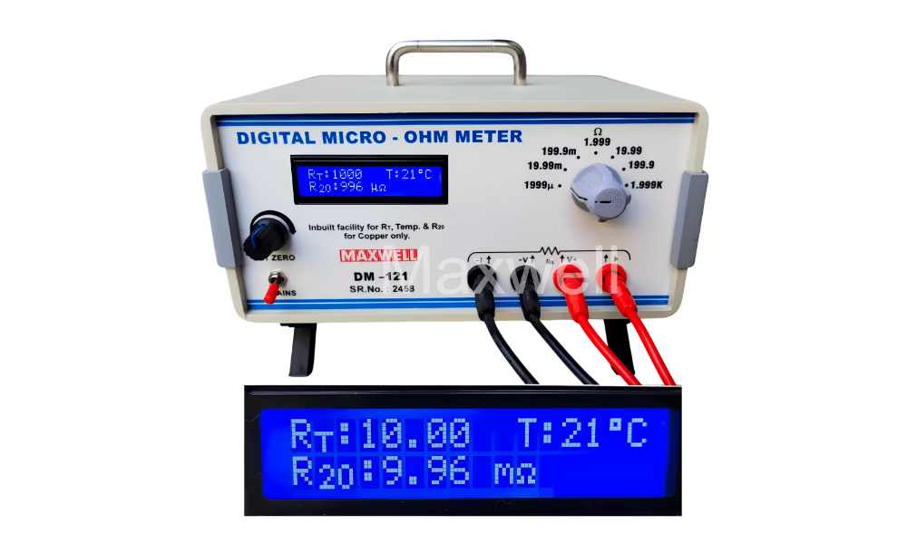
At the heart of every digital micro ohm meter is the 4-terminal Kelvin measurement method. Instead of using two leads, the instrument uses four separate connections — two current terminals (C1, C2) and two potential or sense terminals (P1, P2).
Here’s how it plays out in practice:
- Current injection — A known, stable current is passed through the conductor using the outer current terminals (C1 and C2).
- Voltage sensing — The inner potential terminals (P1 and P2) measure the voltage drop across the conductor, completely separate from the current path.
- Resistance calculation — Using Ohm’s Law (R = V/I), the instrument calculates resistance from the sensed voltage and the known current.
Because almost no current flows through the sense leads, their resistance and any contact resistance at the probe tips barely affect the reading. What you get is the actual resistance of the conductor, not the resistance of your test setup.
Applying a Known Test Current
Most digital micro ohm meters, including Maxwell’s DM-121, apply a test current of up to 2A on lower resistance ranges, dropping to a lower current on higher ranges. A higher test current produces a larger, more measurable voltage drop even across very small resistances, which is what allows the instrument to resolve values down to the micro-ohm level with confidence.
Digital Signal Processing and Display
Once the voltage drop is sensed, the instrument’s internal circuitry converts it into a digital resistance value, which is then shown on the display — typically a bright LED or LCD screen depending on the model. This removes the interpretation errors that come with analog needle-based meters and gives a direct, stable reading.
Temperature Compensation
Resistance in conductors changes with temperature, which can make comparing readings across different testing conditions difficult. This is why many digital micro-ohm meters, such as the DM-121, come with an inbuilt temperature sensor that automatically calculates the resistance at a standard 20°C reference (commonly referred to as R20) as per required in IS 8130 or IS 10810 Part 5, removing the need for manual correction charts or calculations. It is primarily used for testing resistance in a cable/conductor/transformer.
Step-by-Step: How a Typical Measurement Is Taken
- Connect the four terminals — the current terminals(C1 & C2) go on the outer ends of the conductor, and the potential terminals(P1 &P2) go on the inner points where the actual measurement is needed. Please note P1 terminal is placed along with C1 & C2 with P2 otherwise readings will not be shown correctly.
- Set zero — Set zero can be done on 2 ranges i.e.1999µ & 19.99 m and for other values Set zero is not required. On any of these 2 ranges disconnect any one of the Current wire for example C1 and keep the cable/conductor sample connected and now use the Set Zero knob so that the reading shows zero on the screen, so that any residual offset in the leads is nulled out before testing.
- Apply current and measure — the instrument passes current and captures the resulting voltage drop.
- Read the result — the resistance value is displayed digitally, often along with the temperature-compensated R20 value.
This entire process typically takes just a few seconds per test point, which is why these meters are so widely used in repetitive production and quality control testing. Do not use for prolonged use because the current supplied by micro ohm meter can heat up the sample and actual resistance of the sample might change if connected with meter for long duration.
Note: The warm up time of this meter ranges from 1 min to 3 minutes. So connect the leads after the warm up time only for accurate measurement.
Why the 4-Wire Method Matters So Much
It’s worth pausing on this because it’s the single biggest reason a digital micro ohm meter gives trustworthy readings where a multimeter can’t.
In a 2-wire setup, lead resistance and contact resistance sit directly in series with the resistance you’re trying to measure — and at low resistance values, they can easily be larger than the actual reading. The 4-wire Kelvin arrangement separates the current path from the voltage-sensing path, so those errors are effectively cancelled out. This is the same principle behind the Kelvin Double Bridge, a classic instrument still used for calibration and high-precision resistance work.
Common Applications of Digital Micro Ohm Meters
Because of this precision, digital micro ohm meters show up across a fairly broad set of industries:
- Cable and conductor manufacturing — verifying copper and aluminium conductor resistance as per IS 8130 or IS 10810 Part 5
- Transformer and motor testing — checking winding and coil resistance
- Switchgear and circuit breaker testing — measuring contact resistance to catch worn or poorly seated contacts
- Busbar and joint testing — confirming low-resistance connections in power distribution systems
- General quality control — routine low-resistance checks in electrical component manufacturing
What to Look for When Choosing One
If you’re evaluating a digital micro ohm meter for your lab or production line, a few things are worth checking:
Measurement range and resolution — make sure it covers the resistance values you actually work with, down to the resolution you need.
Test current — a higher test current on lower ranges generally improves reading stability, especially for very small resistances.
Terminal arrangement — confirm it uses a genuine 4-terminal Kelvin configuration rather than a 2-wire setup with a “low resistance” label.
Temperature compensation — an inbuilt sensor with automatic R20 calculation saves a lot of manual correction work, particularly for cable testing as per IS standards.
Build and portability — bench-top models suit lab environments, while compact, rugged designs are better for field or shop-floor use.
Digital Micro Ohm Meters at Maxwell
Maxwellindia manufactures digital micro-ohm meters, including the DM-121, designed for cable, conductor, and electrical component testing. These instruments use the 4-terminal Kelvin method, apply a test current suited to accurate low-resistance measurement, and include automatic temperature compensation to display resistance at the standard 20°C reference — all aimed at giving consistent, repeatable readings in lab and production environments.
Conclusion
A digital micro ohm meter solves a problem that regular multimeters simply aren’t built for — measuring extremely small resistance values without the test leads and contact points throwing off the reading. By relying on the 4-terminal Kelvin method, applying a known test current, and often compensating for temperature automatically, these instruments deliver the kind of accuracy that cable manufacturing, transformer testing, and switchgear quality control genuinely depend on. Understanding how a digital micro ohm meter works makes it a lot easier to pick the right one — and trust the numbers it gives you.
Frequently Asked Questions
1. How does a digital micro ohm meter differ from a multimeter?
A multimeter uses a 2-wire method, which includes lead and contact resistance in the reading. A digital micro ohm meter uses a 4-terminal Kelvin method that separates current and voltage sensing, giving accurate readings even at very low resistance values.
2. What is the 4-terminal Kelvin method?
It’s a measurement technique using two current terminals and two separate potential (voltage-sensing) terminals, which eliminates the effect of lead and contact resistance on low-resistance readings.
3. Why does a micro ohm meter need temperature compensation?
Conductor resistance changes with temperature, so an inbuilt temperature sensor that calculates resistance at a standard 20°C reference allows readings to be compared consistently, regardless of ambient conditions. It is required as per IS 8130 or IS 10810 Part 5.
4. What test current do digital micro ohm meters typically use?
Many models apply a test current of up to 2A on lower resistance ranges and a lower current on higher ranges, which helps produce a measurable voltage drop even for very small resistances.
5. Where are digital micro ohm meters commonly used?
They’re widely used in cable and conductor manufacturing, transformer and motor winding testing, switchgear and circuit breaker contact checks, and busbar or joint resistance testing.
6. Why do many laboratories still use Kelvin Double Bridge over Micro-ohm meter in India?
The Bureau of Indian Standards (BIS), India’s National Standards Body, continues to mandate the use of Kelvin Double Bridge instruments in cable testing laboratories, making them a widely used and trusted instrument for cable and conductor resistance testing.
In addition to their use for routine testing, Kelvin Double Bridges provide an independent means of verifying resistance measurements. In some instances, inspectors have identified inaccurate or manipulated readings from micro-ohm meters in cable testing laboratories. Since a Kelvin Double Bridge is a manually operated precision measurement instrument, it offers a reliable and transparent method for cross-checking resistance values.
For this reason, having a Kelvin Double Bridge in the laboratory is highly recommended as an additional verification tool, helping maintain measurement accuracy, testing confidence, and the integrity of test results.